Description
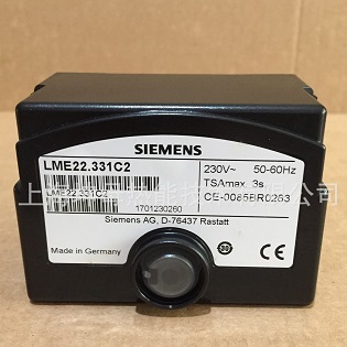
Siemens LME22.331C1 Burner control, 2-stage, ion, t1=30s, TSA=3s, actuator 12s, AC110V
Burner controls LME…for the supervision of 1- or 2-stage gas or gas/oil burners of small to medium capacity, with or without fan in intermittent operation.
The LME… is designed and built for use by OEMs which integrate the burner controls in combustion control products.
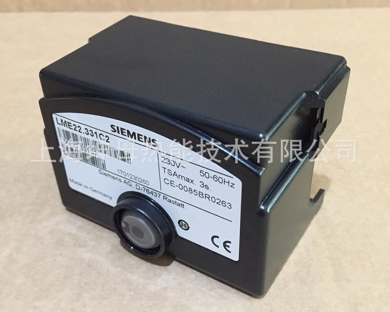
SIEMENS LME22.331C1 burner control
Use
LME… are used for the startup and supervision of 1- or 2-stage gas or gas/oil burners in intermittent operation. The flame is supervised by an ionization probe or flame detector QRA… with ancillary unit AGQ3…A27 for gas/oil forced draft burners or blueburning flames with blue-flame detectors QRC…
In terms of housing dimensions, the LME… are identical with the burner control LGB…and LMG… burner controls
- For gas burners with or without fan to EN 298: 2003
- For gas forced draft burners to EN 676
- For oil burners to EN 230: 2005-10
Feature
- Undervoltage detection
- Air pressure supervision with functional check of the air pressure switch during startup and operation
- Electrical remote reset facility
- Multicolor indication of fault status and operational status messages
- Limitation of the number of repetitions
- Accurate control sequence thanks to digital signal handling
- Controlled intermittent operation after 24 hours of continuous operation
Engineering Notes
- When used in connection with actuators, there is no position feedback signal from the actuator to the burner control
- When used in connection with actuators, the requirements of applicable norms and regulations must be observed
- The running times of the actuators must match the burner control’s program. An additional safety check of the burner control together with the actuators is required
- When substituting burner controls type LGB… or LMG… by LME…, the AGQ1… or AGQ2… ancillary unit must be replaced by the AGQ3…A27
Electrical connection of flame detectors
It is important to achieve practically disturbance- and loss-free signal transmission:
- Never run detector cables together with other cables
– Line capacitance reduces the magnitude of the flame signal
– Use a separate cable - Observe the permissible length of the detector cables
- The ionization probe and ignition electrode are not protected against electric shock hazard
- Locate the ignition electrode and the ionization probe such that the ignition spark cannot arc over to the ionization probe (risk of electrical overloads) and that it cannot adversely affect the supervision of ionization
- Insulation resistance
– Must be a minimum of 50 MΩ between ionization probe and ground
– Soiled detector holders reduce the insulation resistance, thus supporting creepage currents - Earth the burner in compliance with the relevant regulations,earthing the boiler alone does not suffice
More types
LME11.230C2 / LME11.330C2 / LME21.130C1 / LME21.130C2 / LME21.230C2 / LME21.330C1
LME21.330C2 / LME21.350C1 / LME21.350C2 / LME21.550C2 / LME22.131C2 / LME22.231C2
LME22.232C2 / LME22.233C2 / LME22.331C1 / LME22.331C2 / LME23.331C2 / LME23.351C2
LME41.051C2 / LME41.052C2 / LME41.053C2 / LME41.054C2 / LME41.071C2 / LME41.091C2
LME41.092C2 / LME44.056C2 / LME44.057C1 / LME44.057C2
 WhatsApp +8613906047998